Simulation
Forming processes
Identify faults before they occur
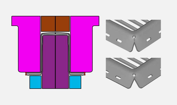
Our simulations rely on more than 20 years’ experience in terms of simulation and method planning. Thanks to our simulations, we can see “into the future”, i.e. even before actually building the tool, and recognise via the simulation how the tool will behave later in the forming process.
Problems are identified and rectified in advance, thereby also increasing the technical maturity of the component, and safeguarding the method as a whole.
Thanks to the FEM pre-processors and solvers we use, we are able to cover all types of simulations. This is not just restricted to “normal sheet metal forming”, but extends to other areas, such as strength and deflection calculations.
Technologies used
- AutoForm (with Autoform Incremental Solver)
- Altair Hypermesh as a pre-processor in conjunction with the FEM solvers LSDYNA or RADIOSS
Shell or solid elements
In our simulations, we use two different element types depending on the application. In simulations where a uniform sheet thickness is required for the component, a shell element is used in most cases.
If various sheet thicknesses are specified for the component, or if high degrees of forming exist as a result of the process, then the simulation is generated with solid elements. This also allows, for example, the multi-stage forming of rim holes to be reliably simulated.
Springback calculation / bounce behaviour
We calculate the theoretical bounce behaviour, and work out compensation proposals with the client, which we then implement in the appropriate effective area.
Hot forming / press-hardening
In addition to traditional cold forming, we also have experience in the field of simulating hotforming processes.
Hot forming involves a heated plate being formed in a cooled press, and then hardened during a subsequent cooling period.
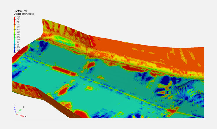
The simulation allows the final component hardness to be calculated, as well as the detection of cracks and wrinkles. Another variant is to heat up a cold-formed component, which is then placed in a cooled tool. In this case, the component hardness after the cooling period – as provided by the simulation – is of particular significance.
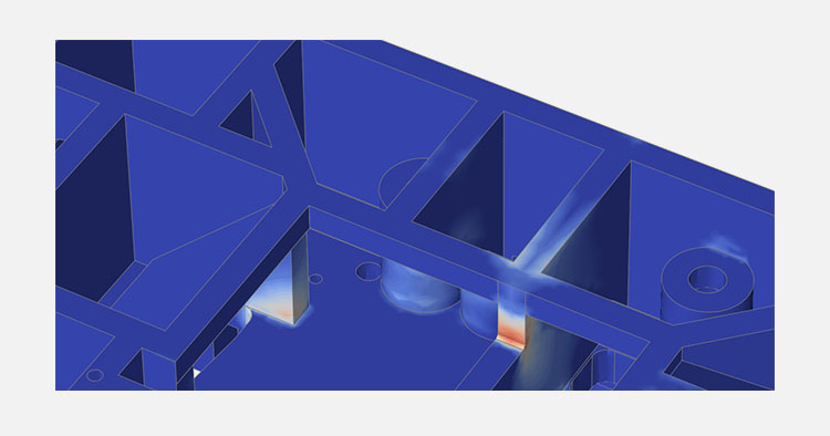
With both simulation methods, areas are identified which experience little contact pressure (e.g. vertical component walls). We can focus on these and work to counteract this phenomenon in the design of the effective areas.
CFD cooling simulation
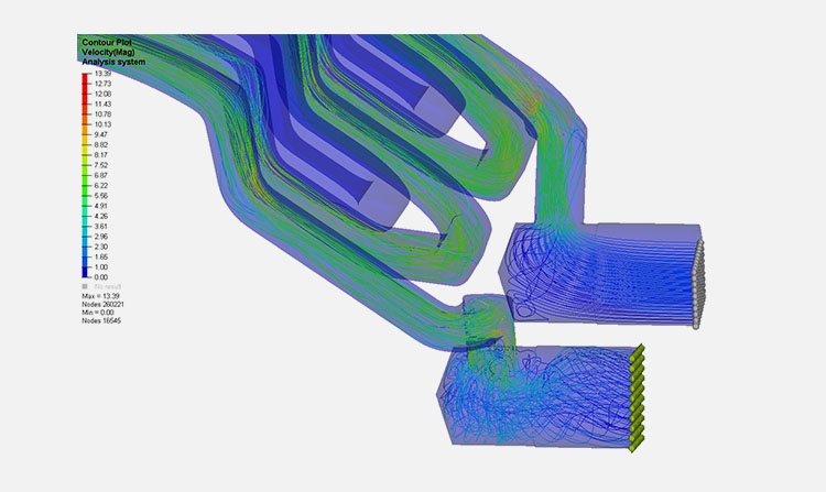
When designing hot forming tools, the designer determines cooling bores to the best of his knowledge. The justified questions often arise: is the cooling bore design so optimal? Is the volume flow the same in all cooling bores? Are there hotspots in the tool that prevent uniform cooling/hardening of the workpiece?
We can provide an answer to these questions even before your tools are manufactured.
If the problems do not arise until the finished tool has been tested, it is almost impossible to change the cooling holes later due to the hardening of the tools. A change can usually only be solved by manufacturing a new tool. We will check your finished design and make suggestions for optimisation if required.
Deflection calculation / strength calculation
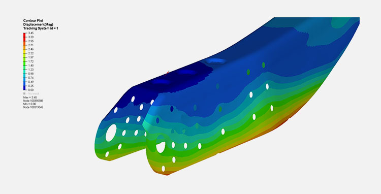
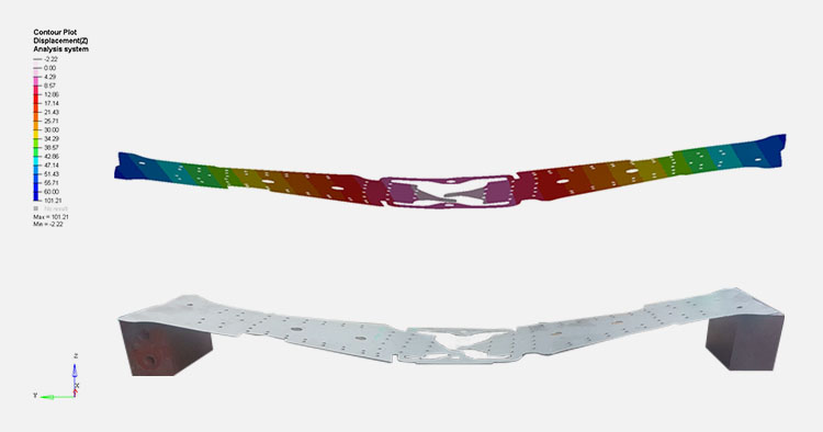
The tools are subjected to large forming forces during the production process. Is the design of the tool cast correct, and will it bear the strain? What levels of deflection should I reckon with? We calculate the deflection and strength of your tools and highlight your points of failure.
Deflections during transfer
How does the moulding or the strip behave in the subsequent tool when transferred to the next tool stage? Is the moulding stiff enough to be transported without issue?
We can answer this question via our simulation. We can examine your moulding or strip, and analyse the transfer behaviour. As required, we can also, for example, optimise them by stiffening. In this way, you can avoid surprises when trialling tools, and reduce the running-in period for them.
DOE – Robustness analysis
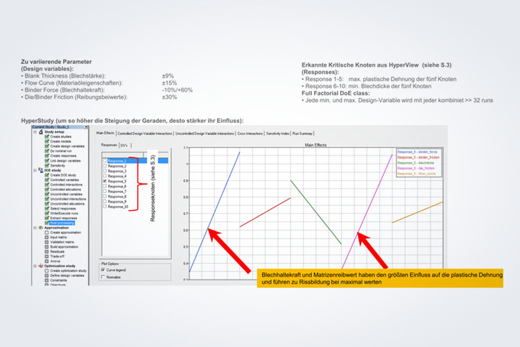
Through our systems, we can also evaluate fluctuations of the input parameters in the production process.
A few parameters are given here by way of example:
- Sheet metal thickness fluctuations
- Differences in the strength in the sheet metal processed
- Friction caused by uneven oiling
Following the analysis, we can provide an evaluation of the robustness of the production process, and also a weighting of the individual parameters that affect the process.
Hydroforming
Through our systems, we can also evaluate fluctuations of the input parameters in the production process.
Hydroforming
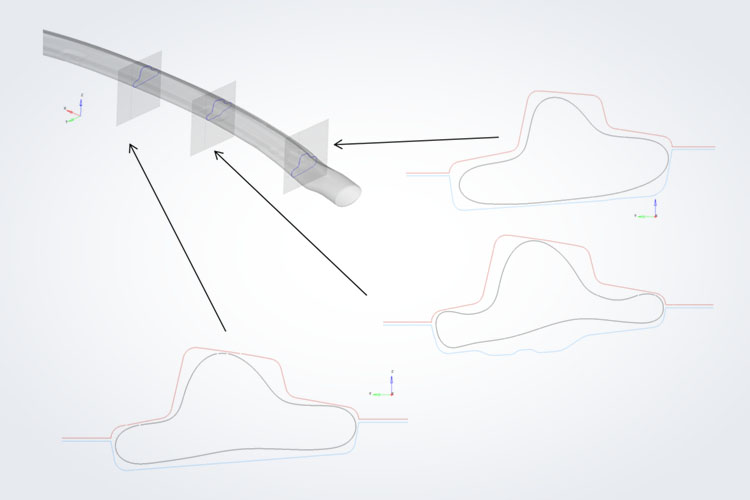
During hydroforming, the component achieves the correct form by means of internal pressure.
External high-pressure forming (hydro mechanical deep-drawing)
A second procedure is external high-pressure forming, whereby the pressure is applied to the outer area of the sheet metal.
Both procedures can be demonstrated using the simulation.


